IS-IS was initially designed by the ISO and is used as a routing protocol based on CLNP addressing. CLNP is a Layer 3 protocol in the OSI reference model posed by the ISO.
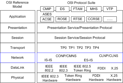
OSI uses systemized (or hierarchical) addressing. The services at the transport layer in OSI can be addressed through the Network Service Access Point (NSAP).
The following terms are commonly used in OSI:
- CLNS: indicates the Connectionless Network Service.
- CLNP: indicates the Connectionless Network Protocol.
- CMNS: indicates the Connection-Mode Network Service.
- CONP: indicates the Connection-Oriented Network Protocol.
OSI implements CLNS through CLNP, and implements CMNS through CONP.
CLNS is implemented through the following protocols:
- CLNP: is similar to the IP protocol in TCP/IP.
- IS-IS: is the routing protocol of an intermediate system.
- ES-IS: is the protocol used between a host system and an intermediate system. It is similar to ARP or ICMP in IP.
Table 1 lists OSI concepts and the equivalent IP concepts.
| Abbreviation | OSI Concept | Equivalent IP Concept |
|---|---|---|
| IS | Intermediate System | Router |
| ES | End System | Host |
| DIS | Designated Intermediate System | Designated Router (DR) in OSPF |
| SysID | System ID | Router ID in OSPF |
| PDU | Protocol Data Unit | IP packet |
| LSP | Link state Protocol Data Unit | OSPF LSA |
| NSAP | Network Service Access Point | IP address |
With the popularity of TCP/IP, the IETF extended and modified IS-IS in RFC 1195 to support IP routing. This enables IS-IS to be used in TCP/IP and OSI environments. This type of IS-IS is called Integrated IS-IS or Dual IS-IS.
Address Structure of IS-IS
In OSI, the NSAP is an address used to locate resources. The ISO uses the address structure shown in Figure 2, that is, NSAP. NSAP is composed of the Initial Domain Part (IDP) and the Domain Specific Part (DSP). The IDP is equal to the network ID in the IP address, and the DSP is equal to the subnet number and host address in an IP address.
As defined by the ISO, the IDP consists of the Authority and Format Identifier (AFI) and the Initial Domain Identifier (IDI). The AFI specifies the address assignment mechanism and the address format; the IDI identifies a domain.
The DSP consists of the High Order DSP (HODSP), system ID, and NSAP Selector (SEL). The HODSP is used to divide areas; the system ID identifies a host; the SEL indicates the service type.
The lengths of the IDP and the DSP are variable. The maximum length of the NSAP is 20 bytes and its minimum length is 8 bytes.
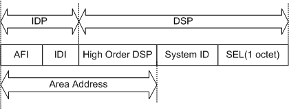
- Area addressThe IDP together with the HODSP of the DSP can identify a routing domain and the areas in a routing domain; therefore, the combination of IDP and HODSP is referred to as an area address, which is equal to an area number in OSPF. There cannot be the same area address in a routing domain, and the Level-1 area addresses of the routers in the same area must be the same.In general, a router can be configured with only one area address. The area address of all nodes in an area must be the same. On the CX600, an IS-IS process can be configured with a maximum of three area addresses for supporting seamless combination, division, and transformation of areas.
- System IDA system ID uniquely identifies a host or a router in an area. In the CX600, the fixed length of the system ID is 48 bits (6 bytes).A router ID has a corresponding system ID. If a router takes the IP address 168.10.1.1 of Loopback 0 as its router ID, its system ID used in IS-IS can be obtained in the following ways:
- Extend each part of the IP address 168.10.1.1 to 3 bits and add 0 to the front of the part that is shorter than 3 bits.
- Divide the extended address 168.010.001.001 into three parts, with each part consisting of four decimal digits.
- The reconstructed 1680.1000.1001 is the system ID.
There are many ways to specify a system ID. During configuration, ensure that the system ID uniquely identifies a host or a router. - SELThe role of an SEL (also referred to as NSAP Selector or N-SEL) is similar to that of the “protocol identifier” of IP. A transport protocol matches an SEL. The SEL is always “00” in IP.
- NETA Network Entity Title (NET) is the network layer information of an IS itself. It does not contain the transport layer information (SEL = 0). A NET can be regarded as a special NSAP. The length of the NET field is the same as that of an NSAP. Its maximum length is 20 bytes and its minimum length is 8 bytes. When configuring IS-IS on a router, you can configure only a NET instead of an NSAP.In general, an IS-IS process is configured with only one NET. When an area needs to be redefined, such as being combined with other areas or divided into sub-areas, you can configure the router with multiple NETs to ensure the correctness of routes.An IS-IS process can be configured with a maximum of three area addresses, and thus a maximum of three NETs can be configured. When configuring multiple NETs, ensure that their system IDs are the same.An example of a NET is ab.cdef.1234.5678.9abc.00, in which the area is ab.cdef, the system ID is 1234.5678.9abc, and the SEL is 00.
/public_sys-resources/icon-note.gif) NOTE:
NOTE:
The routers in an area must have the same area address.
IS-IS PDU Format
The types of PDUs for IS-IS include Hello, LSPs, CSNPs, and PSNPs.
| Type Value | PDU Type | Name |
|---|---|---|
| 15 | Level-1 LAN IS-IS Hello PDU | L1 LAN IIH |
| 16 | Level-2 LAN IS-IS Hello PDU | L2 LAN IIH |
| 17 | Point-to-Point IS-IS Hello PDU | P2P IIH |
| 18 | Level-1 Link State PDU | L1 LSP |
| 20 | Level-2 Link State PDU | L2 LSP |
| 24 | Level-1 Complete Sequence Numbers PDU | L1 CSNP |
| 25 | Level-2 Complete Sequence Numbers PDU | L2 CSNP |
| 26 | Level-1 Partial Sequence Numbers PDU | L1 PSNP |
| 27 | Level-2 Partial Sequence Numbers PDU | L2 PSNP |
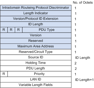
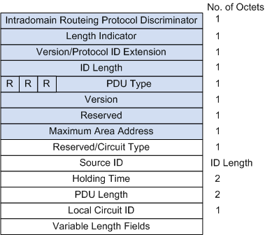
- Hello packet formatHello packets, also called IS-to-IS Hello PDUs (IIH), are used to set up and maintain neighbor relationships. Among them, Level-1 LAN IIHs are applied to the Level-1 routers on broadcast LANs; Level-2 LAN IIHs are applied to the Level-2 routers on broadcast LANs; P2P IIHs are applied to non-broadcast networks. The format of Hello packets varies based on the type of network.Figure 3 shows the format of a Hello packet in a broadcast network (the part in blue is the common header).Figure 4 shows the format of a Hello packet in a P2P network.As shown in Figure 4, most fields in a P2P IIH are the same as those in a LAN IIH. The P2P IIH does not have the priority and LAN ID fields, but has a local circuit ID field. The local circuit ID indicates the local link ID.
- LSP packet formatLink State PDUs (LSPs) are used to exchange link-state information. There are two types of LSPs, that is, Level-1 LSPs and Level-2 LSPs. Level-1 IS-IS transmits Level-1 LSPs; Level-2 IS-IS transmits Level-2 LSPs; Level-1-2 IS-IS can transmit both Level-1 and Level-2 LSPs.Level-1 and Level-2 LSPs have the same format, as shown in Figure 5.The main fields are described as follows:
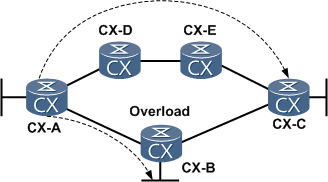
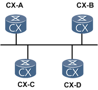
- OL: indicates LSDB overload.LSPs with the overload bit are still flooding the network, but the LSPs are not used when routes that pass through a router configured with the overload bit are calculated. That is, after a router is configured with the overload bit, other routers ignore the router when performing the SPF calculation. Only the direct routes of the router are considered.As shown in Figure 6, packets from CX-A to CX-C are all forwarded by CX-B. If the OL field is set to 1 on CX-B, however, CX-A considers that the LSDB of CX-B is incomplete and forwards the packets to CX-C through CX-D and CX-E, but the packets to the destination that is directly connected to CX-B are forwarded normally.
- IS Type: indicates the type of IS-IS generating the LSP.It is used to specify whether the level of IS-IS is Level-1 or Level-2 (01 indicates Level-1; 11 indicates Level-2).
- OL: indicates LSDB overload.LSPs with the overload bit are still flooding the network, but the LSPs are not used when routes that pass through a router configured with the overload bit are calculated. That is, after a router is configured with the overload bit, other routers ignore the router when performing the SPF calculation. Only the direct routes of the router are considered.
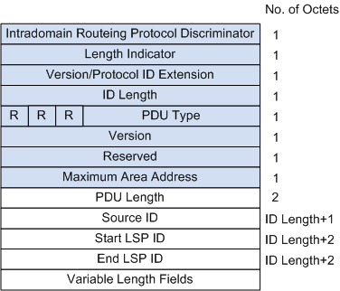
- SNP FormatSequence Number PDUs (SNPs) describe the LSPs in all or part of the databases to synchronize and maintain all LSDBs.An SNP consists of a complete SNP (CSNP) and a partial SNP (PSNP), which are further divided into Level-1 CSNP, Level-2 CSNP, Level-1 PSNP, and Level-2 PSNP.A CSNP contains the summary of all LSPs in an LSDB. This maintains LSDB synchronization between neighboring routers. On a broadcast network, the DIS periodically sends CSNPs. The default interval for sending CSNPs is 10 seconds. On a point-to-point link, CSNPs are sent only when the neighbor relationship is established for the first time.Figure 7 shows the CSNP format.The main fields of a Level-1 or Level-2 CSNP are:
- Source ID: indicates the system ID of the router that sends the SNP.
- Start LSP ID: indicates the ID of the first LSP in the CSNP.
- End LSP ID: indicates the ID of the last LSP in the CSNP.
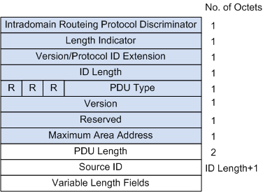
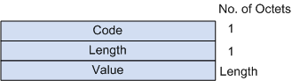
A PSNP lists only the sequence number of recently received LSPs. A PSNP can acknowledge multiple LSPs at a time. If an LSDB is not updated, the PSNP is also used to request a neighbor to send a new LSP.Figure 8 shows the PSNP format. - CLVThe variable length fields in a PDU are the multiple Code-Length-Values (CLVs).Figure 9 shows the CLV format. A CLV is also called the Type- Length-Value (TLV).
CLVs vary with PDU types, as shown in Table 3.
Table 3 PDU types and CLV names CLV Code Name Applied PDU Type 1 Area Addresses IIH and LSP 2 IS Neighbors (LSP) LSP 4 Partition Designated Level2 IS L2 LSP 6 IS Neighbors (MAC Address) LAN IIH 7 IS Neighbors (SNPA Address) LAN IIH 8 Padding IIH 9 LSP Entries SNP 10 Authentication Information IIH, LSP, and SNP 128 IP Internal Reachability Information LSP 129 Protocols Supported IIH and LSP 130 IP External Reachability Information L2 LSP 131 Inter-Domain Routing Protocol Information L2 LSP 132 IP Interface Address IIH and LSP The CLVs with codes ranging from 1 to 10 are defined in ISO 10589 (two types are not listed in the table), and the other CLVs are defined in RFC 1195.

IS-IS Areas
- Two-Level structureTo support large-scale routing networks, IS-IS adopts a two-level structure in a routing domain. A large domain can be divided into one or more areas. In general, Level-1 routers are located in a single area, Level-2 routers are located among areas, and Level-1-2 routers are located between the Level-1 routers and the Level-2 routers.
- Level-1 routerA Level-1 router manages intra-area routing. It establishes neighbor relationships with only the Level-1 and Level-1-2 routers in the same area. It maintains a Level-1 LSDB. The LSDB contains routing information on the local area. A packet to a destination outside this area is forwarded to the nearest Level-1-2 router.
- Level-2 routerA Level-2 router manages inter-area routing. It can establish neighbor relationships with Level-2 routers or Level-1-2 routers in other areas. It maintains a Level-2 LSDB. The LSDB contains inter-area routing information.All Level-2 routers form the backbone network of the routing domain. They are responsible for communications between areas. The Level-2 routers in the routing domain must be configured to ensure the continuity of the backbone network. Only Level-2 routers can exchange data packets or routing information with routers outside the routing domain.
- Level-1-2 routerA router, which belongs to both a Level-1 area and a Level-2 area, is called a Level-1-2 router. It can establish Level-1 neighbor relationships with Level-1 routers and Level-1-2 routers in the same area. It can also establish Level-2 neighbor relationships with Level-2 routers and Level-1-2 routers in other areas. A Level-1 router must be connected to other areas through a Level-1-2 router.A Level-1-2 router maintains two LSDBs, that is, a Level-1 LSDB and a Level-2 LSDB. The Level-1 LSDB is used for intra-area routing and the Level-2 LSDB is used for inter-area routing. NOTE:
Level-1 routers in different areas cannot establish neighbor relationships. Level-2 routers can establish neighbor relationships with each other, regardless of the areas to which they belong. - Interface levelA Level-1-2 router may only need to establish certain neighbor relationships. For example, it can establish only a Level-1 neighbor relationship with the remote end, and a Level-2 neighbor relationship with the other remote end. You can set the level of an interface to restrict the setup of adjacencies on the interface. For example, you can establish only a Level-1 adjacency on a Level-1 interface and only a Level-2 adjacency on a Level-2 interface.
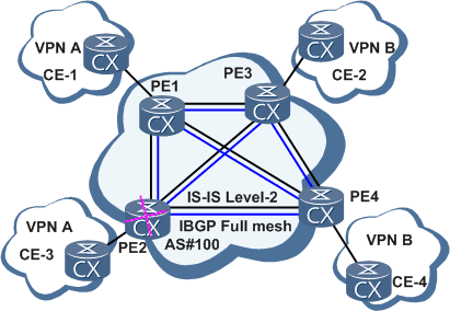
Figure 10 shows a network that runs IS-IS. The network is similar to an OSPF network typology with multiple areas. The entire backbone area contains all routers in Area 1 and Level-1-2 routers in other areas.
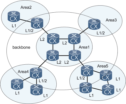
Figure 11 shows another type of IS-IS topology. All the successive Level-1-2 and Level-2 routers form the backbone area of IS-IS. In the topology, Level-2 routers belong to different areas, and Level-1-2 routers also belong to different areas. No area is defined as the backbone area.
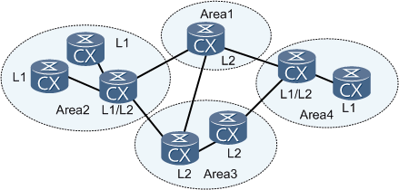
The IS-IS backbone network is not a specific area.
This networking scheme shows the difference between IS-IS and OSPF. For OSPF, inter-area routes are forwarded by the backbone area, and the SPF algorithm is used only in the same area. For IS-IS, both Level-1 and Level-2 routes are calculated by the SPF algorithm to generate the Shortest Path Tree (SPT).
IS-IS Network Types
IS-IS supports only two types of networks. Based on physical links, IS-IS networks can be classified into the following types:
- Broadcast links: such as Ethernet and Token-Ring
- Point-to-point links: such as PPP and HDLC
For a Non-Broadcast Multi-Access (NBMA) network such as ATM, you must configure sub-interfaces as P2P interfaces. IS-IS cannot run on the Point to MultiPoint (P2MP) networks.
DIS and Pseudo Node
In a broadcast network, IS-IS elects a Designated Intermediate System (DIS) from all the routers.
The DISs of Level-1 and Level-2 routers are elected. You can configure different priorities for DISs of different levels. The router with the highest priority is elected as the DIS. If there are multiple routers with the same highest priority in a broadcast network, the one with the largest MAC address is chosen. The DISs of different levels can be the same router or different routers.
Unlike the DR election in OSPF, the DIS election in IS-IS has the following features:
- The router with priority 0 also takes part in the DIS election.
- When a new router that meets the requirements of being a DIS is added, the router is selected as the new DIS. This causes a new flooding of LSPs.
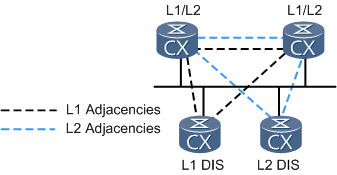
In an IS-IS broadcast network, the routers (including non-DIS routers) of the same level in a network segment set up adjacencies, which is different from that of OSPF. Figure 12 shows the networking.
A DIS is used to create and update pseudo nodes. It also generates LSPs of the pseudo nodes. The LSPs describe the available routers on the network.
The pseudo node is used to simulate a virtual node in a broadcast network and is not an actual router. In IS-IS, a pseudo node is identified by the system ID of the DIS and the 1-byte Circuit ID (its value is not 0).
With pseudo nodes, the network topology is simplified and LSPs are shortened. When the network changes, the number of generated LSPs is reduced. As a result, the SPF consumes fewer resources.
In an IS-IS broadcast network, although all the routers set up adjacencies with each other, the LSDBs are synchronized by the DISs.
Establishment of the IS-IS Neighbor Relationship
Two IS-IS routers need to establish a neighbor relationship before exchanging packets to implement routing. On different networks, the modes for establishing IS-IS neighbors are different.
- Establishment of a neighbor relationship on a broadcast link
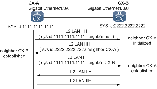
CX-A, CX-B, CX-C, and CX-D are Level-2 routers. CX-A is newly added to the broadcast network. Figure 14 lists the process of establishing a neighbor relationship between CX-A and CX-B. The process of establishing a neighbor relationship between CX-A and CX-C or CX-D is similar to that between CX-A and CX-B.CX-A broadcasts a Level-2 LAN IS-IS Hello PDU. After receiving the PDU, CX-B sets its neighbor status with CX-A to Initial. Then, CX-B responds to CX-A with a Level-2 LAN IIH packet indicating that CX-A is a neighbor of CX-B. On receiving the IIH packet, CX-A sets its neighbor status with CX-B to Up.The network is a broadcast network, so a DIS needs to be elected. After the neighbor relationship is established, routers wait for two intervals for sending Hello packets to elect the DIS. The IIH packets exchanged by the routers contain the Priority field. The router with the highest priority is elected as the DIS. If the routers have the same priority, the router with the largest interface MAC address is elected as the DIS.
- Establishment of a neighbor relationship on a P2P linkThe establishment of a neighbor relationship on a P2P link is classified into two modes: 2-way mode and 3-way mode.
- 2-way modeUpon receiving an IS-IS Hello packet, a router sets up a neighbor relationship in one direction, as shown in Figure 15.
- 3-way modeA neighbor relationship is established after IS-IS Hello PDUs are sent three times, which is similar to the establishment of a neighbor relationship on a broadcast link. NOTE:
The three-way handshake mechanism of IS-IS is explained in other chapters.
Rules for establishing an IS-IS neighbor relationship are as follows:
- Only the neighboring routers of the same level can set up a neighbor relationship with each other.
- Level-1 routers must have the same area ID.
- Routers are on the same network segment.
IS-IS runs on the data-link layer and was initially designed for CLNP. Therefore, the establishment of an IS-IS neighbor relationship is not related to IP addresses. On the CX600, IS-IS runs only over IP and needs to check the IP address of its neighbor. If secondary IP addresses are assigned to the interfaces, the routers can still set up an IS-IS neighbor relationship only when either the primary IP addresses or secondary IP addresses are on the same network segment.
When IP address unnumbered is not configured, if the IP address of its neighbor and the address of the interface through which the router receives packets are not on the same network segment, the neighbor relationship cannot be set up. The neighbor relationship can be set up if you configure the router not to check the IP addresses contained in received Hello packets.
- For P2P interfaces, you can configure the interfaces not to check the IP addresses.
- For Ethernet interfaces, you must simulate Ethernet interfaces as P2P interfaces and then configure the interfaces not to check the IP addresses.
Process of Exchanging IS-IS LSPs
- LSP floodingThe flooding of LSPs is a mode in which a router sends an LSP to its neighbors and the neighbors send the received LSP to their respective neighbors except the router that first sent the LSP. In this manner, the LSP is flooded among the routers of the same level. Through flooding, each router of the same level has the same LSP information and keeps a synchronized LSDB.Each LSP has a 4-byte sequence number. When a router is started, the sequence number of the first LSP sent by the router is 1. When a new LSP is generated, the sequence number of the LSP is equal to the sequence number of the previous LSP plus 1. The greater the sequence number, the newer the LSP.
- Causes of LSP generationAll routers in the IS-IS routing domain can generate LSPs. The following events trigger the generation of a new LSP:
- A neighbor goes Up or Down.
- A related interface goes Up or Down.
- Imported IP routes change.
- Inter-area IP routes change.
- An interface is assigned a new metric value.
- Periodical updates occur.
- Processing of a new LSP received from a neighbor
- The router installs the LSP to the LSDB and marks it with flooding.
- The router sends the LSP to all interfaces except the interface that received the LSP.
- The neighbors flood the LSP to their neighbors.
- Process of synchronizing LSDBs between a newly added router and DIS
- A newly added CX-C sends Hello packets to establish neighbor relationships with the other routers in the broadcast domain. For details, see “Establishment of a neighbor relationship on a broadcast link.”
- After setting up neighbor relationships with other routers, CX-C sends its LSP to the following multicast addresses after the LSP timer expires:Level-1: 01-80-C2-00-00-14Level-2: 01-80-C2-00-00-15All neighbors on the network receive the LSP.
- The DIS on the network segment adds the LSP received from CX-C to its LSDB. After the CSNP timer expires, the DIS sends CSNPs to synchronize the LSDBs on the network. By default, CSNPs are sent at intervals of 10 seconds.
- After CX-C receives the CSNPs from the DIS, CX-C checks its LSDB and sends a PSNP to request the LSPs it does not have.
- After receiving the PSNP, the DIS sends the required LSPs to synchronize LSDBs.
- Process of updating the LSDB of the DIS
- When the DIS receives an LSP, it searches the LSDB for the related records. If the DIS does not find the LSP in its LSDB, it adds the LSP to its LSDB and broadcasts the contents of the new LSDB.
- If the sequence number of the received LSP is greater than the sequence number of the corresponding LSP in the LSDB, the DIS replaces the LSP with the received LSP in the LSDB, and broadcasts the contents of the new LSDB.
- If the sequence number of the received LSP is smaller than the sequence number of the corresponding LSP in the LSDB, the DIS sends the LSP in the LSDB to the inbound interface.
- If the sequence number of the received LSP is equal to the sequence number of the corresponding LSP in the LSDB, the DIS compares the Remaining Lifetime of the two LSPs. If the received LSP has a smaller Remaining Lifetime than the corresponding LSP in the LSDB, the DIS replaces the LSP in the LSDB with the received LSP, and broadcasts the contents of the new LSDB.
- If the sequence number of the received LSP is equal to the sequence number of the corresponding LSP in the LSDB, the DIS compares the Remaining Lifetime of the two LSPs. If the received LSP has a greater Remaining Lifetime than the corresponding LSP in the LSDB, the DIS sends the LSP in the LSDB to the inbound interface.
- If both the sequence number and the Remaining Lifetime of the received LSP and the corresponding LSP in the LSDB are the same, the DIS compares the checksum of the two LSPs. If the received LSP has a greater checksum than the corresponding LSP in the LSDB, the DIS replaces the LSP in the LSDB with the received LSP, and advertises the contents of the new LSDB.
- If both the sequence number and the Remaining Lifetime of the received LSP and the corresponding LSP in the LSDB are the same, the DIS compares the checksum of the two LSPs. If the received LSP has a smaller checksum than the corresponding LSP in the LSDB, the DIS sends the LSP in the LSDB to the inbound interface.
- If both the sequence number, Remaining Lifetime, and checksum of the received LSP and that of the corresponding LSP in the LSDB are the same, the LSP is not forwarded.
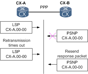
- Process of synchronizing the LSDB on a P2P link
- For the establishment of the neighbor relationship, see “Establishment of the Neighbor Relationship on a P2P Link.”
- When a neighbor relationship is set up for the first time, a router sends a CSNP to its neighbor. If the LSDB of the neighbor and the CSNP are not synchronized, the neighbor sends PSNP requests for a required LSP.
- The router sends the required LSP to the neighbor and starts the LSP retransmission timer. The router then waits for a PSNP from the neighbor as an acknowledgement of the receiving of the LSP.
- If the router does not receive the PSNP from the neighbor after the LSP retransmission timer expires, it resends the LSP.
NOTE:
A PSNP on a P2P link functions as:
- An Ack packet to acknowledge the received LSP.
- A request packet to require LSPs.
- Process of updating the LSDB
- If the sequence number of the received LSP is greater than the sequence number of the corresponding LSP in the LSDB, the router adds the LSP to its LSDB. The router then sends a PSNP to acknowledge the received LSP. Finally, the router sends the LSP to all its neighbors except the neighbor that sent the LSP.
- If the sequence number of the received LSP is smaller than the sequence number of the corresponding LSP in the LSDB, the router directly sends its LSP to the neighbor and waits for a PSNP from the neighbor as an acknowledgement.
- If the sequence number of the received LSP is the same as the sequence number of the corresponding LSP in the LSDB, the router compares the Remaining Lifetime of the two LSPs. If the received LSP has a smaller Remaining Lifetime than the corresponding LSP in the LSDB, the router adds the LSP to its LSDB. The router then sends a PSNP to acknowledge the received LSP. Finally, the router sends the LSP to all its neighbors except the neighbor that sends the LSP.
- If the sequence number of the received LSP is the same as the sequence number of the corresponding LSP in the LSDB, the router compares the Remaining Lifetime of the two LSPs. If the received LSP has a greater Remaining Lifetime than the corresponding LSP in the LSDB, the router directly sends its LSP to the neighbor and waits for a PSNP from the neighbor.
- If both the sequence number and the Remaining Lifetime of the received LSP and the corresponding LSP in the LSDB are the same, the router compares the checksum of the two LSPs. If the received LSP has a greater checksum than the corresponding LSP in the LSDB, the router adds the LSP to its LSDB. The router then sends a PSNP to acknowledge the received LSP. Finally, the router sends the LSP to all its neighbors except the neighbor that sent the LSP.
- If both the sequence number and the Remaining Lifetime of the received LSP and the corresponding LSP in the LSDB are the same, the router compares the checksum of the two LSPs. If the received LSP has a smaller checksum than the corresponding LSP in the LSDB, the router directly sends its LSP to the neighbor and waits for a PSNP from the neighbor.
- If both the sequence number, Remaining Lifetime, and checksum of the received LSP and the corresponding LSP in the LSDB are the same, the LSP is not forwarded.

No comments:
Post a Comment