Purpose
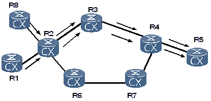
In a traditional IP network, a node select the shortest path as the route regardless of other factors such as bandwidth. The shortest path, however, may be congested with traffic, whereas other available paths are idle.As shown in Figure 1, assume that links have the same metric. The shortest path from R1 (R8) to R5 is R1 (R8) -> R2 -> R3 -> R4 -> R5. Data is forwarded along this shortest path though other paths to R5 are available. The situation may occur that the path R1 (R8) -> R2 -> R3 -> R4 -> R5 is congested due to overload, and the path R1 (R8) -> R2 -> R6 -> R7 -> R4 -> R5 is idle.
Network congestion is the major cause of poor performance of a backbone network. The congestion is caused by insufficient resources or unbalanced load of network resources. Traffic engineering (TE) solves the problem of congestion caused by unbalanced loading. Traditional TE solutions to congestion are as follows:
- TE controls the network traffic by adjusting the metric of a path. This can eliminate congestion of only part of links, and cause the congestion on other links. In addition, in a network with complicated topology, the metric is difficult to adjust because the change of a link may affect multiple routes.
- TE directs partial traffic by setting up virtual connections (VCs) based on an overlay model. The current Interior Gateway Protocols (IGPs) are topology driven and applicable to only static network connections regardless of the dynamic factors such as bandwidth and traffic characteristics.The overlay model such as IP over Asynchronous Transfer Mode (ATM) and IP over Frame Relay (FR) can complement IGP disadvantages. The overlay model provides the virtual topology over the physical topology for a network. This helps to reasonably adjust traffic and implement Quality of Service (QoS) features. The overlay model, however, is of high cost and low scalability.
Definition
MPLS TE is an abbreviation for MPLS Traffic Engineering. In MPLS TE, a constraint-based label switched path (CR-LSP) can be set up according to the Resource Reservation Protocol-TE (RSVP-TE). The constraints include the bandwidth, priority, affinity attribute, explicit path, and hop limit. In addition, a CR-LSP can be set up statically, that is, a static CR-LSP.By integrating MPLS with traffic engineering, MPLS TE can reserve resources by setting up LSPs along a specified path to detour congested nodes and balance network traffic.
MPLS offers the following features required by TE implementation:
- MPLS supports explicit paths to control the paths of LSPs.
- MPLS uses the signaling to set up LSPs, which are easy to configure and convenient to maintain.
- Setting up LSPs consume a few resources; therefore, the establishment of LSPs does not affect other network services.
- Network traffic is easily mapped to an LSP.
- The behaviors of an LSP can be easily controlled by the attributes of the LSP such as priority and preemption.
- The administrative group attribute and affinity attribute can control the path of an LSP.
- MPLS allows traffic aggregation and disaggregation, which is more flexible than IP forwarding.
- MPLS can easily generate constraint-based routes.
To ensure continuity of services, MPLS TE introduces the CR-LSP backup mechanism and fast reroute (FRR) mechanism. When faults occur on a link, traffic can be switched in time.
The attributes related to MPLS TE are as follows:
- CR-LSPA CR-LSP is the LSP that is set up on basis of certain constraints. A common LSP is set up on the basis of routing information. In addition to routing information, a CR-LSP can be set up when other requirements, such as the specified bandwidth, selected path, and QoS parameters are met.
CR-LSPs are classified into the following types:
- Static CR-LSP: Forwarding information and resource information are manually configured for a CR-LSP regardless of signaling protocols or path calculation. Setting up a static CR-LSP costs few resources because two ends of the CR-LSP do not need to exchange MPLS control packets. The static CR-LSP, however, cannot be adjusted dynamically according to the changeable network topology and hence is not widely used.
- Dynamic CR-LSP: It is set up and maintained through the signaling mechanism. Path calculation is required during the setup of a dynamic CR-LSP.
- RSVP-TERSVP is extended to RSVP-TE for the setup of a CR-LSP.
- BandwidthBandwidth is one of basic attributes of MPLS TE. Before a CR-LSP is set up, the path of a CR-LSP is selected according to the specified bandwidth. The RSVP-TE signaling carries the bandwidth information and reserves bandwidth on each node along the path. After a CR-LSP is set up, the CR-LSP can provide sufficient bandwidth for the specific service.
- Explicit pathA CR-LSP can be set up over a specified path. This path is called an explicit path. Explicit paths are classified into the following types:
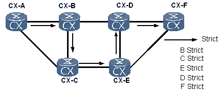
- Strict explicit pathA strict explicit path contains the nodes through which a CR-LSP passes and one hop of the CR-LSP must be directly connected to the next hop. By strictly specifying an explicit path, you can most exactly control the path of a CR-LSP.
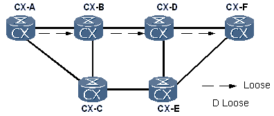
As shown in Figure 2, LSRA is the ingress, and LSRF is the egress. An LSP from LSRA to LSRF is set up along a strict explicit path. "B strict" indicates that this LSP must pass through LSRB, and the previous hop of LSRB is LSRA. "C strict" indicates that this LSP must pass through LSRC, and the previous hop of LSRC is LSRB. The rest may be deduced by analogy, and then you can precisely control the path through which the LSP passes. - Loose explicit pathA loose explicit path contains the specified nodes through which an LSP must pass; however, other routers can exist between nodes.
As shown in Figure 3, an LSP is set up over a loose explicit path from the ingress LSRA to the egress LSRF. "D loose" indicates that this LSP must pass through LSRD; however, other routers can exist between LSRD and LSRA. That is, LSRA and LSRD do not need to be directly connected.
- Strict explicit pathA strict explicit path contains the nodes through which a CR-LSP passes and one hop of the CR-LSP must be directly connected to the next hop. By strictly specifying an explicit path, you can most exactly control the path of a CR-LSP.
- Priority and preemptionWhen you set up a CR-LSP, if no path has sufficient bandwidth, an established CR-LSP with a lower priority is torn down and the bandwidth resources assigned to that CR-LSP are used. This is called preemption.
CR-LSPs use two priority attributes, namely, setup priority and holding priority, to determine whether to preempt resources. The value of the priority is an integer ranging from 0 to 7. The smaller the value, the higher the priority. The value 7 indicates the lowest priority. - Administrative group and affinity attributesAn administrative group is a 32-bit vector representing a set of link attributes.
The affinity attribute is a 32-bit vector representing the color of a tunnel link. After the CR-LSP is configured with the affinity attribute, the router compares the affinity attribute with the administrative group attribute during link selection to determine whether to select or detour the path with the specified attributes.
After the affinity attribute is configured on the ingress, the affinity attribute is sent to each node along a CR-LSP through RSVP-TE. - Hop limitHop limit is used to select a path for the CR-LSP to be set up. Similar to the administrative group attribute and affinity attribute that can limit a CR-LSP, it limits the number of hops that a CR-LSP allows
check other IP RAN Technology and ISIS TE
No comments:
Post a Comment